This is an easy DIY project, which will add safety to your CNC setup for $30 or less.
The purpose of this Safety main switchboard is that it controls the power to your CNC as well as the router or LASER, and has a kill-switch to turn off everything at once in case of an emergency. Let’s hope that big red button is never needed; but if it is, this setup may save you from a dangerous disaster.
An additional convenient feature is that this setup allows you to toggle the power supply to either the router or the LASER (not both) that is mounted onto your CNC machine, using a key that can also be turned to an OFF position (where neither the router nor the LASER receives power), and then taken out for safekeeping. This setup works even if you have a variable speed controller to regulate the spindle RPM of your router.
Here’s what the Safety main switchboard will look like:
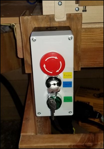
A large red mushroom kill-switch, a key switch to toggle between router or LASER, and a green push-lock button to power the CNC machine.
What you need
- A momentary mushroom, key switch, self-lock push button box as shown in the picture above (for instance from Amazon).
- An 8 ft indoor/outdoor extension cord of at least 16 gauge, 13 A, 125 V (for instance from Home Depot or Lowe’s).
- Two 15 A, 125 V female cord outlets (for instance from Home Depot or Lowe’s).
- Tools (electrical cable wire stripping tool and a Phillips screwdriver).
This is what the Safety main switch board looks like when opened up:
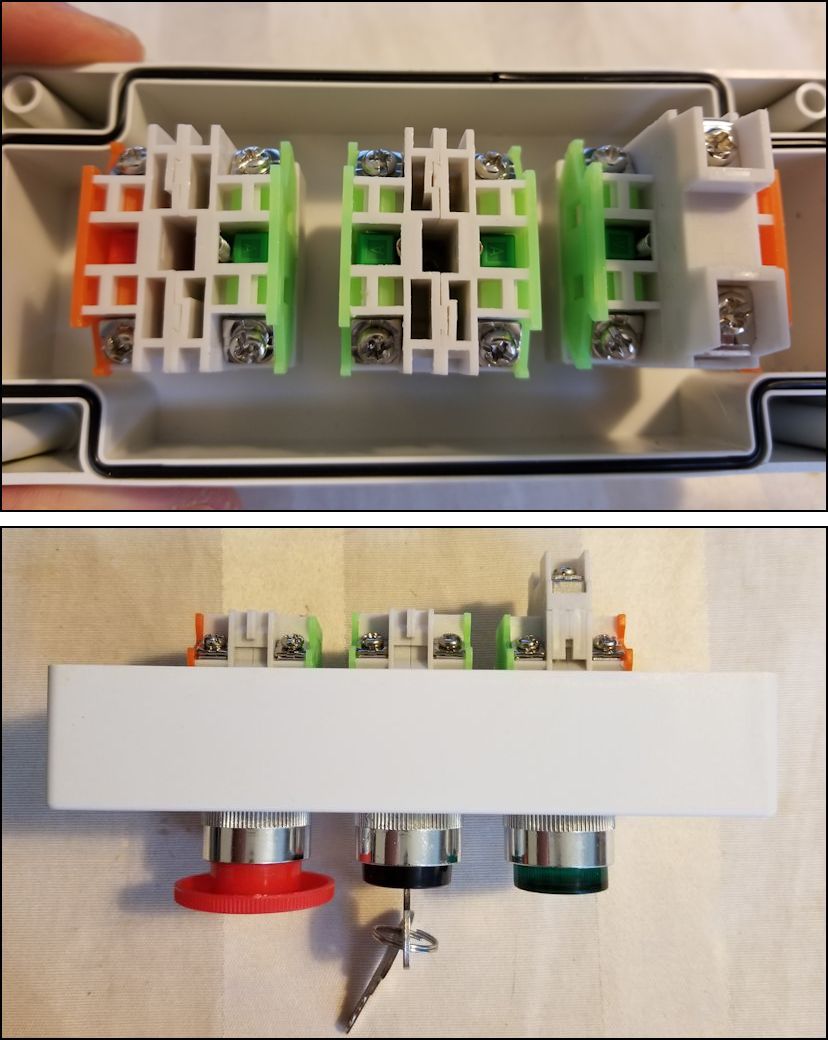
Safety main switchboard when opened up: back view (top) and side view (bottom).
Cutting the electrical cords
First, cut the extension cord in half. The end with the male plug will be used to connect the Safety main switchboard with a wall socket outlet.
Cut another 10-12 inch from both extension cord halves; together with the female extension cord half, these two extra pieces of cord will become the 3 plugs protruding from the Safety main switchboard box to connect your CNC machine, router and LASER. In my case, I needed the long cord to connect with my LASER, as its power adapter cord was shorter than the CNC machine’s and router’s power cords.
Strip the ends of the electrical cords, so that they can be fastened to the switch units with the screw clamps. Also, cut 3 pieces of extra wire, each with a length of about 2 inch, and strip their ends; these will be used for internal wiring.
Connecting the electrical cords
Use the diagram below to connect the electrical cords to their designated switch units, following the wire color-coding of your country.
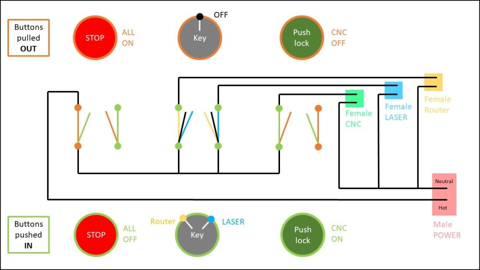
I labeled the wire ends protruding from the Safety main switchboard box with colored stickers as follows:
- Yellow = Router
- Blue = LASER
- Green = CNC machine
Attaching the female plugs
One of the cords already has a female plug attached (in my case, that was the LASER wire). Attach the other two female plugs to the stripped cord ends protruding from the Safety main switchboard box, and label them so that you know which one is for the CNC machine, the router and the LASER.
I also labeled the male plugs from the CNC machine, the router and the LASER with the same colors, so that I can easily recognize which male plug goes into which female plug.

In this picture, you can see only the CNC machine (green) and the router (yellow) male and female plugs connected. The LASER wire (blue) with female plug coming from the Safety main switchboard is longer to meet the LASER male plug somewhere else. The power cable with the male plug is plugged into a wall socket outside this picture.
Note that, if your router is plugged into a variable speed controller, it is the male plug from that variable speed controller which should be connected to the female plug from the Safety main switchboard.
Now your setup is complete!
Operating the Safety main switchboard
- The big red Mushroom kill-switch should be pulled out (some need to be turned to pop out) to power the rest of the circuit.
- Then push in the green button to power your CNC.
- Now choose to activate either the router or the LASER by turning the key counter-clockwise or clockwise.
- When done with your project, follow the steps in reverse to switch everything off (the key goes in the middle position for OFF).
- In case of an emergency, simply hit the kill switch and everything will turn off. Make sure that the key switch and the CNC button are in the OFF position before pulling out the kill switch to reactivate your setup.